
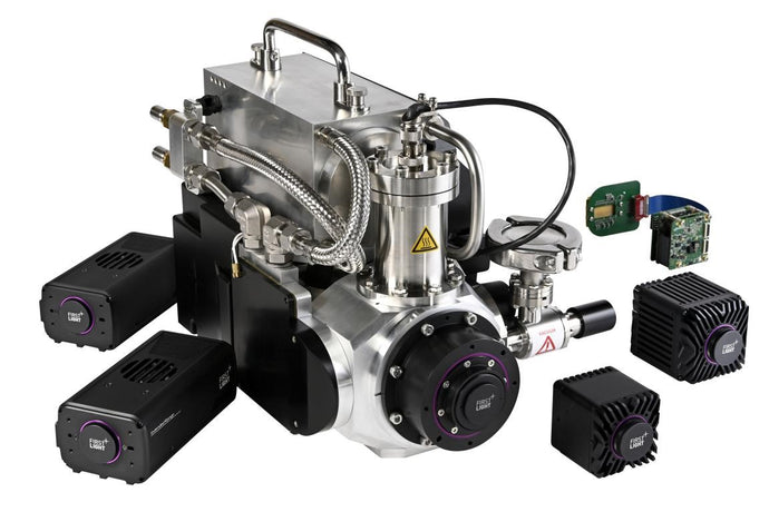
Alrad is a provider of high quality scientific equipment to industry, research and medical establishments. Our main product areas cover Machine Vision components, Optical Detectors, Laser Products, Thermal Imaging and Medical equipment.
Trading since 1970 we are based in Newbury in Berkshire in the south of England.
Through our five trading divisions, Alrad Imaging, Alrad Electronics, Alrad Photonics, Alrad Thermal and Alrad Medical we offer thousands of product items from the world's leading manufacturers. We also provide installation, demonstration, and product support services.
Many of our principals we represent as a sole distributor in the UK. Some of these exclusive companies have been with us since the 1970s so you see many of our distribution agreements have been in place for a very long time and that must say something about the service we offer. The products and service we provide open up new opportunities for our customers to improve quality, automation, productivity and service and that is why many of our existing customers have been experiencing ALRAD high quality service for decades.
Alrad employ experienced staff to help our customers generate a competitive edge for their companies backed by world class products.
BENEFITS OF BUYING FROM ALRAD
ALRAD has knowledgeable and well trained staff who have many years of applications experience in the fields of Machine Vision, Industrial Imaging,Photonics, Electronics and Medical products.
We have a wealth of suppliers from across the globe whom are experts in their product field
Our suppliers are leaders in new technology
Alrad is a leading member of the UK Industrial Vision Association who are Britain's most foremost vision group
Buy from Experts - Buy with confidence.


Quality Assurance
Alrad has a history of passionately striving to provide its customers with the best possible service.
The suppliers we use are all vetted via our in-house quality management system which is recognised by ISO9001:2015 certification through the Approachable Registered organisation.
Learn More